How to Use Relay Server Management - AnySecura Manual
This guide will help you manage the relay servers in your AnySecura deployment, ensuring they are properly authorized and configured to handle client connections. You'll learn how to navigate to the Relay Server Management console and control which relays are active.
Once your relays are authorized, you can fine-tune their operation by setting management scopes, configuring traffic policies, and enabling advanced features like load balancing. This allows you to optimize network performance and maintain a secure, efficient relay architecture.
When deploying a relay architecture, the server can connect to multiple relays. Go to Tools > Server Management > Relay Server Management to manage the relays connected to the server.
Authorization
After setting the relay's connection parameters, it must be authorized from the console connected to the corresponding server.
In the console, go to Tools > Server Management > Relay Server Management, select the relay in the structure tree on the left, and choose Authorize from the right-click menu. Once successful, the relay's status in the display view on the right will change to Authorized. To revoke authorization, select an authorized relay, right-click, and choose Cancel Authorization; the relay will return to the Unauthorized status.
View Basic Information
Select the main server and choose Basic Information to view its details, including:
| Property Name | Description |
|---|---|
| Status Information | Information about the main server's status |
| Name | Always displayed as <Main Server> |
| Network Address | The IP address of the main server machine |
| Version | The current version of the main server |
| Total Agents Connections | Total number of clients connected to the main server |
| Online Agents | Number of clients currently online and connected to the main server |
Select the repeater and choose 'Basic Information' to view the basic information of the repeater, including:
| Property Name | Description |
|---|---|
| Status Information | Information about the relay's status |
| Name | The relay name shown > Server Management > Relay Server Management; defaults to the relay machine's computer name and can be renamed in the console |
| Computer | The computer name of the relay machine |
| Applicant | The applicant set when configuring the relay's connection parameters |
| Network Address | The IP address of the relay machine |
| Running Status | Includes: "Unauthorized, disconnected from main server," "Connected, not authorized," "Connected, authorized" |
| Start Time | The time the relay was started |
| Uptime | The duration the relay has been running since startup |
| Connection Status | The connection status with the main server. Displays Connected if successful, Failed if there is an issue |
| Last Connection Time | The most recent time the relay connected to the main server |
| Authorization Status | Whether the main server has authorized the relay: Authorized or Unauthorized |
| Authorization Update Time | The last time the main server updated the relay's authorization |
| Total Client Connections | Total number of clients connected to the relay |
| Online Clients | Number of clients currently online and connected to the relay |
| Scope Settings | Scope configuration information of the relay |
| Management Scope | The management scope assigned to the relay |
| Exclusion Scope | The exclusion scope assigned to the relay |
Scope Settings
Select Scope Settings to configure the relay's management scope, exclusion scope, and other related settings.
| Setting | Description |
|---|---|
| Management Scope | Sets the range of client IP addresses the relay can manage.
|
| Exclusion Scope | Sets the range of client IP addresses excluded from relay management.
|
| Active Polling | If checked, the relay server will actively connect to port 8235 of clients within the management scope. If unchecked, the server will not actively connect to clients.
|
Pre-Forwarding Traffic
Pre-forwarding traffic settings use traffic policies to limit communication between the main server and relays.
Various management operations can be performed on the policies:
| Icon Button | Description |
|---|---|
 |
New——Click to create a new policy |
| Modify——Click to modify a selected policy | |
 |
Delete——Click to delete a selected policy |
 |
Move Up——Move the selected policy up one position |
 |
Move Down——Move the selected policy down one position |
Click the New button to configure traffic settings and data types, creating a new traffic policy. Multiple traffic policies can be created. After setting or modifying a policy, click the Save button ![]() to apply the changes.
to apply the changes.
The parameters for creating a new pre-forwarding traffic policy are as follows:
| Parameter | Description |
|---|---|
| Traffic Settings | |
| Restriction Time | The time period when the policy is effective, including: All day, Work hours, Rest hours, Weekends, or Custom. Time categories can also be pre-defined in Time Category Management. |
| Limit Relay-to-Server Traffic | Restricts traffic sent from the relay to the main server (KB/s). Enter an integer value. If unchecked, no limit is applied. |
| Limit Relay Receive Traffic | Restricts traffic received by the relay from the main server (KB/s). Enter an integer value. If unchecked, no limit is applied. |
| Limit Total Send/Receive Traffic | Restricts the combined send and receive traffic between the relay and the main server (KB/s). Enter an integer value. If unchecked, no limit is applied. |
| Data Types | |
| Prohibited Data Types | If checked, select the specific data types to block. During the restriction time, the selected data types will be prohibited for sending and receiving. If unchecked, no data type restrictions are applied. |
Policy Matching Principle
Policies are matched from top to bottom. Once a valid policy is matched, only that single policy takes effect, and no further policies are evaluated.
Note:
- A policy is considered valid when it is checked (enabled).
Post-Forwarding Traffic
Post-forwarding traffic settings use traffic policies to limit communication between a relay and its connected clients.
| Icon Button | Description |
|---|---|
|
New——Click to create a new policy |
| Modify——Click to modify a selected policy | |
|
Delete——Click to delete a selected policy |
|
Move Up——Move the selected policy up one position |
|
Move Down——Move the selected policy down one position |
Click the New button to set the network address, restriction time, and traffic settings, creating a new traffic policy. Multiple policies can be created. After setting or modifying a policy, click the Save button ![]() to apply the changes.
to apply the changes.
The parameters for creating a new policy are as follows:
| Parameter | Description |
|---|---|
| Network Address | The network address range where the policy applies. Options include: All, LAN, WAN, Enterprise Network, Internet. Custom ranges can also be defined in Category Management. |
| Restriction Time | The time period when the policy is effective, including: All day, Work hours, Rest hours, Weekends, or Custom. Time categories can also be pre-defined in Time Category Management. |
| Traffic Settings | |
| Total Traffic | Limits the total traffic for all IPs within the network address range. You can restrict traffic sent from the relay to clients, received from clients, or the combined send/receive traffic. Each value is an integer; leaving it unset means no limit. |
| Per-IP Traffic | Limits traffic for each individual IP within the network address range. You can restrict traffic sent from the relay to clients, received from clients, or the combined send/receive traffic. Each value is an integer; leaving it unset means no limit. |
Policy Matching Principle:
Policies are matched from top to bottom. Each IP will match only one Per-IP Traffic limit and one Total Traffic limit.
- 1. Policies are matched according to priority.
- 2. Each policy can include both Total Traffic and Per-IP Traffic limits. When a policy is matched, both the total and per-IP traffic restrictions are applied simultaneously.
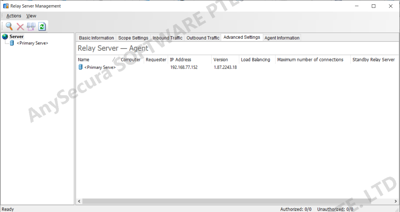
Advanced Settings
Advanced settings allow configuration of load balancing for relay servers, maximum number of connections, and whether the relay server is designated as a backup.
| Property Name | Description |
|---|---|
| Enable Load Balancing | Check this option to enable load balancing.
|
| Rated Connections | Default is 1000; can be adjusted.
|
| Specified Load Rate | Default is 0; can be set to another value.
|
| Maximum Connections | The maximum number of clients that can connect to this relay. Default is unchecked; if enabled, the default maximum is 3000, and it can be set to another value. |
| Set as Backup Relay | Check this option to designate the relay as a backup. Clients will connect to it only if all regular relays are unreachable. If the backup relay is also unreachable, clients will connect to the main server. If unchecked, the relay functions as a regular relay.
|
Note:
- 1. Clients perform load balancing only among relays with the same connection priority level.
- 2. Load rate is calculated as: current connections ÷ rated connections.
Load Balancing Example 1
Within the company, Relay A and Relay B are deployed, each capable of handling all 1,500 clients. Without load balancing enabled, Relay A connects to 1,000 clients, while Relay B connects to 500 clients.
Scenario 1: Relay A and Relay B Have Similar Performance
Load balancing can be configured as follows:
- Enable load balancing on Relay A, set rated connections to 1000, and specified load rate to 0.
- Enable load balancing on Relay B, set rated connections to 1000, and specified load rate to 0.
Effect:
Relay A's load rate is 1000 ÷ 1000 = 100%, and Relay B's load rate is 500 ÷ 1000 = 50%. Since Relay A's specified load rate is 0 and its load rate is higher than Relay B's, some clients on Relay A will migrate to Relay B until the load is balanced.
Scenario 2: Relay A Has Higher Performance than Relay B
In this case, more clients can connect to Relay A.
Policy 1:
- Enable load balancing on Relay A, set rated connections to 2000, specified load rate to 0.
- Enable load balancing on Relay B, set rated connections to 1000, specified load rate to 0.
Effect:
Relay A's load rate is 1000 ÷ 2000 = 50%, and Relay B's load rate is 500 ÷ 1000 = 50%. Both relays have the same load rate, so clients do not switch. The higher-performance Relay A handles more clients than the lower-performance Relay B.
Alternatively, without changing rated connections, adjusting the specified load rate allows Relay A to handle more clients than Relay B.
Policy 2:
- Enable load balancing on Relay A, set rated connections to 1000, specified load rate to 120.
- Enable load balancing on Relay B, set rated connections to 1000, specified load rate to 0.
Effect:
Relay A's load rate is 1000 ÷ 1000 = 100%, and Relay B's load rate is 500 ÷ 1000 = 50%. Although Relay A's load rate is higher than Relay B's, it does not exceed its specified load rate of 120%, so clients on Relay A will not migrate.
Agent Information
Select Agent Information to view details of clients connected to the current server or relay.
| Field Name | Description |
|---|---|
| Name | The name displayed in the computer tree. Can be renamed for easier management; if not changed, it defaults to the computer name. |
| Computer | The client's actual computer name. |
| Computer Group | The group to which the client belongs. |
| Network Address | The IP address used for communication between the client and the server/relay. |
| Status | The client's current status: Running, Offline, or Client Uninstalled. |
| Last Online Time | The last time the client communicated with the server/relay. |
| Access Server | The name of the server or relay the client is connected to. |